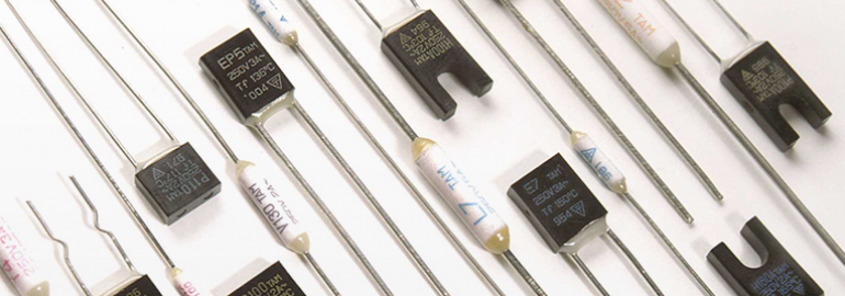
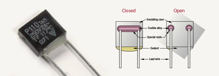
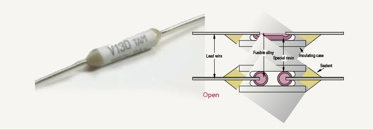
 Thermal cutoffs are single action devices that open when a preset temperature is reached. They do not reset. The active component of a thermal cutoff is a fusible alloy surrounded by a special resin. Under normal operating temperatures the fusible alloy joins the two lead wires within the body of the cutoff. When the preset temperature of the cutoff is reached, the fusible alloy melts and with the aid of the special resin, complete cutoff is ensured. Thermal cutoffs are available in both Axial and Radial configurations as shown and with current ratings from 1/2 Amp to 7 Amps.
 Details & Specifications
Radial type
Axial type
Terminology
Functioning Temperature (TF)
The temperature at which a thermal cutoff changes its state of conductivity to open a circuit with detection current of 10mA or less as the only load. The temperature tolerance for the UL and CSA standard is +0°C / -10°C.
Holding Temperature (TH)
The maximum temperature at which a thermal cutoff can be maintained while conducting rated current for 168 hours without functioning.
Maximum Temperature (TM)
The maximum temperature at which mechanical and electrical properties of a thermal cutoff can be maintained for 10 minutes without resuming conductivity after functioning.
NOTE: Select Axial and Radial cutoffs are available with a special higher temperature sealant making these devices suitable for automatic wave soldering. Devices possessing this characteristic are noted as “designed for automatic wave soldering.”


Precautions When Using Thermal Cutoffs
The following information describes the correct methods of using thermal cutoffs to insure proper and safe performance. To achieve the full use and capacity of a thermal cutoff, it is necessary for the customer to exercise proper storage and ex- ecute appropriate circuit design, proper installation, and adequate testing. Thermtrol Corporation does not assume responsibility for problems which occur as a result of improper storage and installation, or inappropriate circuit design, evaluations or tests.
- Do not use thermal cutoffs for purposes other than for what they are intended. Thermal cutoffs operate only when they sense an ambient temperature greater than the factory pre-set temperature. They have no ability to function by current overload and are not current limiting devices.
- Do not use thermal cutoffs in equipment, appliances or devices in- tended to be used in the aerospace industry, aviation, nuclear power generation systems, life support systems, engine control systems, or safety control systems for transportation. Thermal cutoffs are ap- plicable for electrical household devices, appliances and electronics. Other applications include: office automation equipment, audio/visual equipment, communication systems, measuring instruments and specific transportation systems.
- Do not use thermal cutoffs in applications exceeding the listed ratings in the specification charts.
- Do not use thermal cutoffs in a liquid, in a corrosive atmosphere such as sulfurous gas, or in a high humidity environment.
- Customers shall choose the thermal cutoff appropriate for the application and determine the proper mounting position and/or method. To judge whether the selected thermal cutoff and chosen position and method of mounting is suitable for the final application, we recommend that the customer fully test and evaluate the unit in an environment that duplicates the final application as closely as possible. This includes mounting and securing the thermal cutoff identically to the method that will be used in production.
Handling and Installation Instructions
When using thermal cutoffs, considerable caution should be exercised as follows:
Installation
- Mount the thermal cutoff in a location where uniform radiation of heat is sustained over the body of the unit.
- Keep the leads as long as possible to maximize the area of exposure to heat.
- Place and connect the thermal cutoff in a manner so that no ex- ternal mechanical force will be applied to the body and/or leads of the cutoff.
- Allow adequate space for mounting the thermal cutoff.
Lead Bending
- When bending a lead, bend at a location 3mm minimum from the body of the thermal cutoff. See below.
- Take caution not to damage either the thermal cutoff body or the lead.
- Keep the thermal cutoff body free from any push, pull or twist force.

Soldering
NOTE: The special sealant joining the lead wires to the case will soften during soldering. Care must be taken to not move the leads or body during the soldering process as the softened joints could shift and become disconnected. The sealant will resume its initial strength after cooling.- Minimize the conduction of excessive heat to when soldering the thermal cutoff body
- Maximum soldering time is shown below.
- During soldering, both the thermal cutoff body and leads should be free of any push, pull or twist force.
- After manual soldering, allow the thermal cutoff to cool for 30 seconds minimum without moving it. Automatic wave soldered units must cool for a minimum of 5 minutes.
